
The following describes how to assemble the StashCan in a step-by-step process.
Please note that lubrication is extremely beneficial to the operation of the StashCan and should be applied where indicated in the following instructions. When indicated please use a light synthetic oil such as Super Lube 51004 Synthetic Oil with PTFE or similar.
200 Middle Assembly (the “Can Assembly”)
Step 1: Thread Lock Installation
Install “204 Thread Lock” into “201 Can”. The thread lock presses into the slot on the inside wall of the Can from the top end of the Can.

Step 2: Gravity Latch Installation
Install “203 Gravity Lock” into “201 Can”. The Gravity Latch installs from the bottom end of the can by flexing it slightly into the slot shown. The up arrow on the side of the Gravity Latch indicates the top end of the can.
CHECK: Ensure the Gravity Latch moves freely back and forth when the can is inverted and re-inverted.
Lubrication – A small amount of lubricant can be applied to the sides of the Gravity Latch if needed to ensure smooth operation.

Step 3: Can Liner Installation
While the Can is still inverted, slide the “202 Can Liner” into the Can with the open end of the Can Liner towards the top of the Can. Take note to match the recesses on the Can Liner to the thread Lock and Gravity Latch.
CHECK: Once the Can Liner is installed, ensure the Gravity Latch moves freely back and forth when the can is inverted and re-inverted.

300 Bottom Assembly (the “Lock Assembly”)
Before building the Lock Assembly it is beneficial to understand how the lock is coded so that you can code it while building it. If you have not done so already, please read the Coding the Lock page before proceeding.
Step 4: Ring Spring Installation
Install the three “341 Ring Springs” onto the “361 Lock Housing” as illustrated. When installing the Ring Springs ensure the recessed edge of the Ring Springs are oriented downward to create a small gap under and between each Ring Spring as labelled [A]. The tabs on the Ring Springs should hook onto the edges of the Lock Housing as labelled [B].
Lubrication – Apply a small amount of lubricant to the inside walls of the Ring Springs to ensure the Lock Disks (to be installed later) move freely against the Ring Springs.
CHECK: Check the recesses on the Ring Springs are oriented downward as illustrated and that each Ring Spring is sitting properly on the Lock Housing.

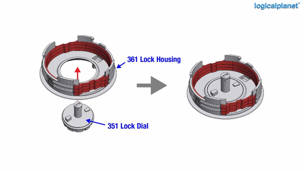
Step 5: Lock Dial Placement
Place the “351 Lock Dial” on your work surface and then place the “361 Lock Housing” over it so that the Lock Dial is centred under the Lock Housing as illustrated. Note on the top of the Lock Dial are two nubs, one taller and one shorter.
Step 6: Setting the Code for Lock Disk C
Carefully lower the “323 Lock Disk C” onto the shaft of the Lock Dial and rotate it so that the taller nub on the Lock Dial protrudes through the number of your choice on the Lock Disk C. Lock Disk C represents the 3rd code of the combination lock. In the example of a lock combination of 1-2-3, Lock Disk C should be set to “3”.
IMPORTANT: Through the remaining steps of assembling the lock, you must ensure the Lock Dial and the Lock Disk C do not separate unknowingly as it is possible for the position of the nub [A] to move inadvertently consequently changing the 3rd digit of your lock code.

Step 7: Setting the Code for Lock Disk B
If you have not done so already, carefully separate the print support [C] shown in orange, from the “332 Key Disk B” [B]. Ensure that the Key Disk B [B] is clean and free from any small remaining parts of the print support.
After removing the print support from the Key Disk B, note that there is a nub [A] on the underside of the disk.
Place the Key Disk B onto the “322 Lock Disk B” and rotate it so that the nub [A] protrudes through the number of your choice on the Lock Disk B. Lock Disk B represents the 2nd code of the combination lock. In the example of a lock combination of 1-2-3, Lock Disk B should be set to “2”.
CHECK: Ensure that the Key Disk B is pressed into Lock Disk B firmly and is completely flush with Lock Disk B. If the Lock Disk and Key Disk are not seated completely together the lock assembly will not operate properly.
Then place Lock Disk B (with Key Disk B) on the the shaft of the Lock Dial and into the Lock Housing, nested inside the Ring Springs.

Step 8: Setting the Code for Lock Disk A
Note that there is a nub [A] on the underside of the “331 Key Disk A”.
Place the Key Disk A onto the “321 Lock Disk B” and rotate it so that the nub [A] protrudes through the number of your choice on the Lock Disk A. Lock Disk A represents the 1st code of the combination lock. In the example of a lock combination of 1-2-3, Lock Disk A should be set to “1”.
CHECK: Ensure that the Key Disk A is pressed into Lock Disk A firmly and is completely flush with Lock Disk A. If the Lock Disk and Key Disk are not seated completely together the lock assembly will not operate properly.
Then place Lock Disk A (with Key Disk A) on the the shaft of the Lock Dial and into the Lock Housing, nested inside the Ring Springs.

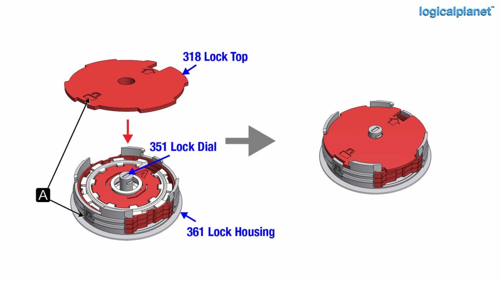
Step 9: Place the Top Onto the Lock Assembly
Note there is a lock symbol [A] on the “318 Lock Top” and a corresponding one on the Lock Housing. Place the Lock Top onto the Shaft of the Lock Dial and into the Lock Housing, nested inside the Ring Springs with the lock symbols [A] aligned.
Step 10: Insert the Lock C Clip
Clip on the “319 Lock C Clip” to hold the entire assembly together. The Lock C Clip is easiest to snap on when laid onto the Lock Top and slid onto the Lock Dial Shaft directly from the side. If the Lock C Clip is restrictively tight or very loose the Lock Assembly has not been assembled properly. Open it, review it and re-assemble it to ensure the Lock C Clip mounts onto the Lock Dial shaft with just a comfortable fit.
If you can not get the Lock C Clip to snap on comfortably the most likely issue is one of the Key Disks not fully seated into the Lock Disk.
Lubrication – A small amount of lubricant can be applied to the underside of the Lock C Clip where it meets the Lock Top to ensure free rotation.
CHECK: Ensure that all the lock disks move freely when the Lock Dial is turned.

Step 11: Verify the Lock Combination
Verify the lock combination now before proceeding to ensure you can open the StashCan once it is assembled. Turn the Lock Dial several times (at least 2 full rotations) clockwise to reset the tumblers (the Lock Disks). Then continue turning clockwise to the first digit of your code and stop. Then rotate counterclockwise past 0 to the second digit of your code and stop. Lastly, rotate clockwise again, to the 3rd digit of your code and stop. At this point, all the Key Disks should be aligned and you should be able to see the inside bottom of the Lock House [B] as illustrated.
IMPORTANT: It is absolutely critical that you ensure your lock combination is working at this point. And, record it somewhere so that it is not forgotten. If you are unable to enter the correct combination later the StashCan will be unopenable.

Step 12: Prepare the Can Assembly
Before the Lock Assembly can be attached to the Can Assembly, the Thread Lock must be in the unlocked position or alternatively stated, the Thread Lock must be slide upward towards the top of the can as illustrated.

Step 13: Install the Lock Assembly to the Can Assembly
With the Thread Lock in the unlocked position, screw the Lock Assembly clockwise onto the bottom of the can. It is most convenient to do this with the Lock Assembly in the unlocked state (all Lock Disks aligned to the open position).

Step 14: Lock the Lock Assembly into the Can Assembly
To prevent the Lock Assembly from being removed from the Can Assembly, slide the Thread Lock downward into the locked position. If you are unable to slide it down, the Lock Assembly is not fully seated.

100 Top Assembly (the Top)
Step 15: Remove the Print Support from the Can Top
If you have not already, remove the print support [B] shown in orange, from the 101 Can Top.

Step 16: Install the Pull Tab
Place the “102 Pull Tab” into the “101 Can Top”. Note there is a small notch on the front of the Pull Tab indicated as [A].

Step 17: Install the Push Down Plate
Note that the “103 Push Down Plate” has a notch [A] that mates with a protrusion [B] on the “101 Can Top”. And, a protrusion C that mates with [D] on the Pull Tab.
Without allowing the Pull Tab to fall out, place the Push Down Plate onto the Pull Tab Shaft and inside the Can Top while ensuring that [A] and [B] and [C] and [D] align.

Step 18: Install the Push Down Spacer
Note that the “104 Push Down Spacer” has a notch [A] that mates with a protrusion [B] on the “101 Can Top”.
Again, without allowing the Pull Tab to fall out, place the Push Down Spacer onto the Pull Tab Shaft and inside the Can Top while ensuring that [A] and [B] align.

Step 19: Install the Lock Spring
Note that the “105 Lock Spring” has a notch [A] that mates with a protrusion [B] on the “101 Can Top”.
Again, without allowing the Pull Tab to fall out, place the Lock Spring onto the Pull Tab Shaft and inside the Can Top while ensuring that [A] and [B] align. The protrusions of the Lock Spring must be inserted into and through the corresponding slots in the Can Top. To accomplish this tilt the Lock Spring to insert one side and insert the first protrusion. Then using a small screwdriver (or similar) flex the second protrusion [C] on the other side inward and down into the corresponding slot in the Can Top.

Step 20: Install the Cam Plate
Place the 106 Cam Plate onto the Pull Tab shaft and inside the Can Top as shown. Ensure the knobs on the top of the Lock Spring are in the larger opening side of the Cam Plate slots as illustrated.
Lubrication – Apply a small amount of lubricant where the knobs of the Lock Spring meet the inside walls of the slots on the Cam Plate.

Step 21: Install the Top C Clip
Snap the “107 Top C Clip” onto the Pull Tab shaft to hold the entire assembly together. The Top C Clip should sit comfortably on the shaft without binding. If there is any binding the top will not work. If you can not get the Top C Clip onto the shaft comfortably one or more of the internal components is not installed correctly.
Lubrication – Apply a small amount of lubricant between the Top C Clip and the Cam Plate.

Step 22: Install the Top Retainer
Install the “108 Top Retainer” into the Can Top by squeezing it together slightly and dropping it into the recess in the inside of the Can Top. If it does not fit comfortably, one or more of the internal components is not installed correctly.
Lubrication – Apply a small amount of lubricant between the Top Retainer and the Cam Plate.
CHECK: Ensure that the top assembly parts all move freely now and that the Top Assembly is working properly.

Step 23: Install the Top Assembly into the Can
The Top Assembly installs in a counter-clockwise rotation to the Can Assembly. However, the Top Assembly can only be screwed on (or off) when the Gravity Latch is fully downward inside the can. The Gravity Latch can only be fully downward when the Bottom Assembly (the Lock) is in the open state (all Lock Disks aligned so that the Gravity Latch is able to fall down to the bottom of the Can.
With the combination lock code entered, the lock open, and the Gravity Latch downward, screw the Top Assembly onto the Can Assembly in a counter-clockwise rotation.

The StashCan is now fully assembled.